Bally Astrocade#

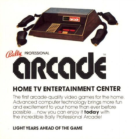
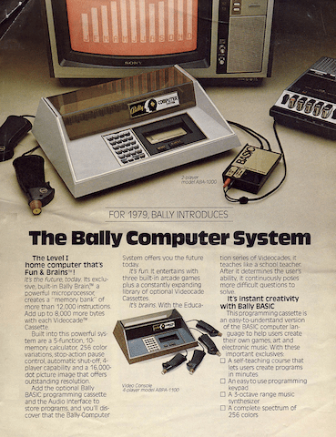
In 1977, Bally/Midway introduced the “Bally Home Library Computer” sold exclusively via mail order. No units were shipped until 1978, where it was renamed the “Bally Professional Arcade” and marketed via retail outlets with the trademarked tagline “Fun & Brains”.
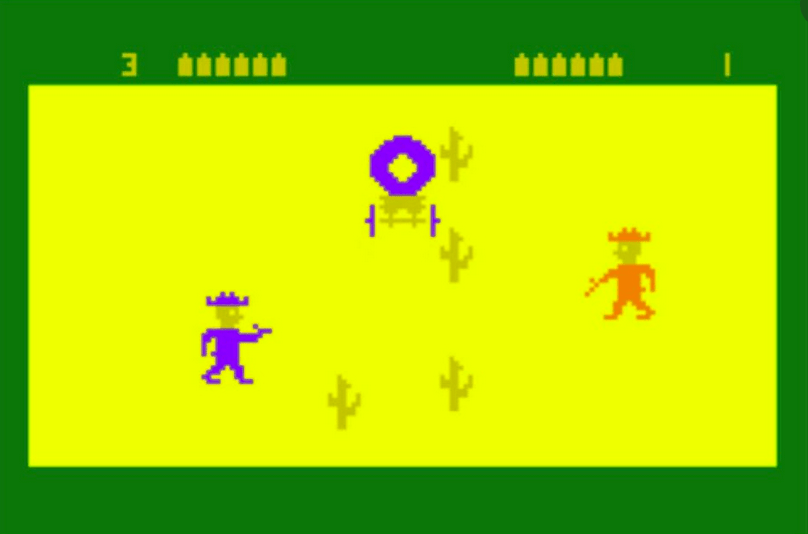
The console had two built-in games which were ports of Midway arcade games – Gunfight and Checkmate. You could also start a “Scribbling” paint program, or use an on-screen calculator.
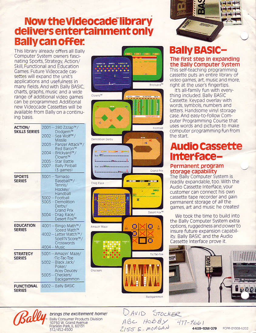
Affixed to the console was a 24-key keypad, used for game menus or for the built-in Calculator app. It could also be used with the Bally BASIC cartridge to write simple games and graphics demos. An audio jack was built into the cartridge, which allowed reading and writing from a cassette tape.
The ambitious system never attained the popularity of the Atari 2600. It had overheating problems (the manual warned against using it on carpet) and poor marketing that couldn’t decide if the product was an awkward BASIC machine or a game console.
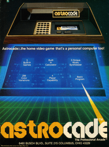
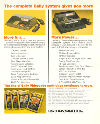
The system was then renamed “Bally Computer System” and sold to Astrovision in 1980, who again renamed the system to “Astrocade: The Professional Arcade” (video).
A more powerful “add-under” expansion called ZGRASS was announced (ZGRASS was a BASIC-like language developed by digital artists at the University of Chicago, supporting advanced graphics and animation primitives). The promised expansion was never released, and Astrocade filed for Chapter 11. However, third party expansions like Blue Ram and the Viper System were available.
!!! Fun Fact: The GRASS language was used to produce the “Death Star plans” animation for the 1977 Star Wars movie.
!!! Another Fun Fact: Jamie Fenton claims that the expansion unit in the National Videogame Museum may actually contain FORTH, not BASIC. Jamie wrote Gorf and Robby Roto in FORTH.
Astrocade CPU and RAM#
The Astrocade is powered by a Zilog Z80 at 1.789 MHz. This is on par with many early microprocessor-based arcade games like Sega’s Carnival.
The design includes a “micro-cycler” architecture that combines the address and data buses into a single bus to reduce the pin count on custom chips. It also sends wait signals to the CPU when the display circuitry is reading from RAM, so programs can write to video memory at any time without corruption.
The Astrocade packed in 8 KB of dynamic RAM, a cavernous amount for the time. The designers used a cost-saving measure pioneered by early Midway arcade games:
“The frame buffer used refresh spec fallout 4K x 1 DRAMs. These were cheap and easy to get at the time because all the manufacturers had problems meeting the refresh specs. Since we read out data during all lines, refresh was no problem. This idea was originated on the original Midway monochrome 8080 based games – Gunfight, Seawolf, etc.” – Tony Miller, Stern Electronics (Berzerk, Frenzy)
Astrocade Graphics#
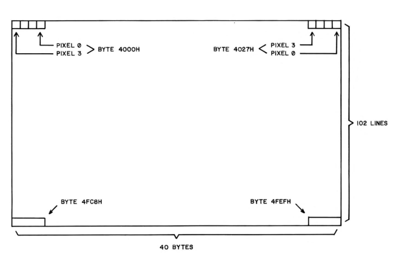
The Astrocade’s frame buffer has a resolution of 160 x 102 pixels. Each pixel can take one of 4 colors, drawn from a palete of 256.
The system palette actually contains 8 colors – the screen can be split vertically at a configurable X coordinate, so that left and right sides show a different set of 4 colors.
At the maximum resolution of 102 scanlines, the frame buffer takes up almost all available RAM, and there are only 16 bytes available for programs, including the stack. Most games display 98 or fewer scanlines to reserve room for the BIOS and stack.
!!! The Bally BASIC used a clever hack to expand the amount of available RAM. Each pixel on the screen was shared – one bit for BASIC, one bit for the display. The palette was set up so that the BASIC bit was ignored, and thus only two colors could be displayed on the screen.
Video Processor, aka Magic Function Generator#
    .---------.                                           .-------.
    | "Magic" |                                           | Video |
 -->| Shadow  |--> Expand --> Shift --> Flop -->  OR   -->| Frame |
    |   RAM   |            or Rotate           or XOR     |  RAM  |
    '---------'                                           '-------'

        * o        * * o o   o o * *   * * o o   * * o o   * * * o
                                                 o * * o
The console included a “video processor” chip developed by Dave Nutting Associates for Midway. It is also called the “Magic System”. The same chip was used in coin-op games like Gorf and Wizard of Wor, but at 320 x 204 resolution.
This chip does not include hardware sprites, but instead accelerates video RAM operations via a function generator. It can be configured to shift, expand, combine, mirror, and/or rotate pixels as they’re written to the frame buffer.
The function generator is accessed via “magic memory” – a memory-mapped region that shadows the frame buffer.
When this region is written to, a sequence of operations are performed according to flags in the hw_magic register.
The resulting byte is then written to the frame buffer.
As far the CPU is concerned, this happens transparently.
Astrocade Sound#
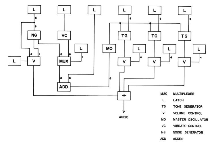
The “music processor” (0066-117xx chip) is similar to the Texas Instruments SN76489 in functionality. It has three square wave channels driven by a master frequency, and a noise generator. There is also a vibrato circuit, which can be distinctly heard in the opening dirge of Wizard of Wor.
You can program the sound registers directly, or ask the BIOS to play music in the background. The music itself is programmed in a special instruction set, executed via a virtual machine (MUZCPU).
!!! You won’t hear vibrato in the 8bitworkshop IDE, because the emulator doesn’t support it yet.
The Astrocade BIOS#
The Astrocade BIOS has a rich set of system functions. These are accessed through the User Program Interface, which defines conventions for calling routines and entering/exiting interpretive mode, which allows multiple commands to be strung together.
The categories of system routines include:
Screen Handler - Handles filling rectangular areas, displaying text and BCD numbers, drawing patterns (bitmaps) and animation.
Human Interface - Handles controller and keypad input, waiting for events, scoring, and menu selection.
Interrupt Scheduler - Handles timers and music.
Math - A set of BCD and decimal math routines, and misc. utility functions.
!!!
The IDE doesn’t use the original Astrocade ROM.
It uses AstroLibre,
our written-from-scratch sort-of-compatible open-source BIOS, so not all calls will be supported,
and the menu system is not available.
The IDE will use an alternate ROM if one is uploaded to the filename astrocade.rom.
Programming the Astrocade in Assembler#
8bitworkshop supports programming the Astrocade in Z80 assembly language using the ZMAC assembler. The assembler uses a set of macros (defined in hvglib.h) to interface with the BIOS.
To save bytes, the BIOS supports “interpreter mode”. This mode executes BIOS routines with a primitive bytecode, relieving us of the burden of placing parameters into registers, and allowing for much more compact code.
To start interpreter mode, we use the SYSTEM INTPC macro:
SYSTEM INTPC ; Begin interpreter mode
This macro generates a RST $38 instruction, which jumps to a subroutine at memory address $38.
The RST instruction pushes the Program Counter (plus 3) onto the stack,
which the interpreter routine uses to find the address immediately following the RST command.
This is where the interpreted routine starts.
Our first command is SETOUT, which does several things:
It sets the Y coordinate where VBLANK starts, thus, the height of the screen.
It also sets the horizontal color boundary, the X coordinate that of the imaginary vertical line that splits the left and right sides of the screen which use two different 4-color palettes.
It sets an interrupt mask, enabling screen interrupts on each frame.
Each interpreter command starts with the DO macro, specifying the routine to execute.
This is followed by either DB (8-bit) or DW (16-bit) parameters, depending on the routine.
SETOUT takes three parameters:
DO      SETOUT          ; Set output ports
DB      100*2           ; ... with VBLANK line set to line 100
DB      112/4           ; ... with color boundary 112 pixels from the left of the screen
DB      00001000b       ; ... with screen interrupts reenabled
Then we set the color palettes with the COLSET command, passing a pointer to an array of color bytes:
DO      COLSET          ; Set color palettes
DW      Palettes        ; ... with the values at Palettes
The FILL command fills the screen (or RAM) with a specific pattern of pixels:
DO      FILL            ; Set background fill
DW      NORMEM          ; ... starting at the beginning of screen RAM
DW      98*BYTEPL       ; ... and going for 100 lines
DB      00010010b       ; ... with a fill pattern of three different colored pixels
We can use STRDIS to display strings in the Astrocade’s built-in font. (You can even enlarge the font by 2x, 4x, or 8x!)
DO      STRDIS          ; Set string display
DB      0               ; ... starting 0 pixels from the left of the screen
DB      32              ; ... and 32 pixels from the top of the screen
DB      00001100b       ; ... with no enlargement, foreground color = 11, background color = 00
DW      PrgName         ; ... to show string at PrgName
After the interpreter encounters an EXIT command, it returns to the address immediately following the EXIT opcode. The CPU takes over from there, and runs Z80 code again.
EXIT ; Exit interpreter mode
Interpreter mode also supports user-defined subroutines, opening up all sorts of possibilities, like a custom scripting language.
If you don’t want to use interpreter mode, you can also pass parameters directly in registers. Calling a routine with the SYSSUK macro reads parameters inline as in interpreter mode, and the SYSTEM macro uses the current registers. You can combine these two approaches, for example:
AnimBars:   SYSSUK  RANGED          ; Load a random 8-bit number in A
            DEFB    0               ; ...
            LD      BC,24*BYTEPL    ; Load BC with one scanline's length
            LD      DE,NORMEM+(72*BYTEPL)
            SYSTEM  FILL            ; Fill remainder of screen with repeating random tile
The Better Bally Book has a detailed list of routines and which registers need to be set for each.
Programming in C#
You can also program in C using the SDCC compiler. The 8bitworkshop IDE provides a rich interface to the Astrocade BIOS from C:
- aclib.h
Defines hardware registers, constants, vidmem/vmagic arrays, and quick macros.
- acbios.h
Defines font descriptors, data structures, BIOS commands and macros.
- acextra.h
Additional graphics operations that don’t require the BIOS.
- acfast.h
“Fast” 8- or 16-pixel-wide sprite-drawing routines.
There are C macros which do SYSTEM calls:
// calls SETOUT command with inline params
SYS_SETOUT(89*2, 23, 0);

// clear screen w/ SYS_FILL macro
SYS_FILL(0x4000, 89*40, 0);
The macros can only be used with constant parameters, because they expand into inline assembly statements.
There are also C functions that can take complex expressions as parameters:
// display standard characters
display_string(2, 2, OPT_ON(1), "HELLO, WORLD!\xb1\xb2\xb3\xb4\xb5");

// add to and display a BCD number
bcdn_add(bcdnum, 3, bcdinc);
display_bcd_number(80, 80, OPT_ON(2), bcdnum, 6|DISBCD_SML|DISBCD_NOZERO);
Drawing Sprites#
![]()
You can draw sprites via the BIOS. First, you define a pattern:
const byte BALL[] = {
    0, 0,		// x and y offset
    1, 6,		// width (bytes) and height (lines)
    /*{w:8,h:6,brev:1}*/
    0b01111000, // line 0
    0b11011100, // line 1
    0b10111100,	// line 2
    0b10111100, // line 3
    0b11111100, // line 4
    0b01111000, // line 5
  };
Then you can draw it at a given X/Y coordinate:
write_relative(50, 80, M_XPAND, BALL);
The M_XPAND constant is used to draw monochrome (1 bit-per-pixel) sprites.
You can omit this flag to draw 4-color (2 bits-per-pixel) sprites.
You can also use the M_OR or M_XOR flags to combine sprites with existing pixels.
Controllers#
The BIOS has a powerful mechanism for waiting for external events and/or interrupts. First, we wait for a code from the SENTRY routine:
// wait for SENTRY result
word code;
do {
  code = sense_transition(ALKEYS);
} while (code == 0);
Then we switch based on the result.
// respond to SENTRY
switch (code & 0xff) {
  case SSEC:
    display_bcd_number(80, 80, OPT_ON(2), bcdnum, 6|DISBCD_SML|DISBCD_NOZERO);
    bcdn_add(bcdnum, 3, bcdinc);
    break;
  case SP0:
    hw_horcb = (code>>8)>>2;
    break;
}
SSEC means “one second has passed” so we increment a BCD counter and draw it to the screen.
SP0 means “paddle 0 moved” so we set the horizontal color boundary according to the paddle position.
Many other options
are possible, incuding waiting for timers and keypad, joystick and trigger changes.
Using the “Magic System”#
Video memory is exposed as 2-dimensional C arrays.
You can write directly to the frame buffer (vidmem) or “magic” memory (vmagic).
To draw a single pixel, we have to find the appropriate byte, by dividing the X coordinate by 4. We then have to shift the pixel color by 0, 2, 4, or 6 bits, depending on the remainder.
We can use the “magic” function generator to accelerate this shift operation.
We set the desired shift amount in the hw_magic register,
and then write to the vmagic space:
void xor_pixel(byte x, byte y, byte col) {
  col <<= 6;			               // color goes in top 2 bits
  hw_magic = M_SHIFT(x) | M_XOR;	   // set magic register
  vmagic[y][x>>2] = col;               // write to destination address
}
Some operations take more than one write to complete.
The M_XPAND option converts each bit into a 2-bit pixel, where off/on values are mapped
to one of two colors, determined by the hw_xpand register.
You can use this to convert a bitmap to a 2-color pattern.
First set up the registers, then write the same byte to two consecutive locations:
    byte* src = &font_char[ch];              // source address
    byte* dest = &vmagic[y][x>>2];           // destination address
    hw_xpand = XPAND_COLORS(0, 1);           // set bg and fg colors
    hw_magic = M_SHIFT(x) | M_XPAND | M_XOR; // set ops: shift, expand, XOR
    *dest++ = *src;                          // write first byte
    *dest++ = *src++;                        // write second byte
Raster Tricks#
Like many of its later-generation peers, the Astrocade supports raster line interrupts.
You just have to set the hw_lin register to tell the hardware at which scanline to trigger the interrupt.
You can even change this register multiple times during a frame for multiple screen splits.
First, set the interrupt handler:
// set our custom interrupt vector
set_interrupt_vector(&intvector);
Our interrupt handler sets the palette colors based on a counter.
Then it updates the hw_lin register so that the next interrupt
will fire four scanlines below the current scanline.
void inthandler(void) __interrupt {
    byte i = linenum;   // get counter
    hw_col0l = i;       // update palette 0
    hw_col1l = i+1;     //            ... 1
    hw_col2l = i+2;     //            ... 2
    hw_col3l = i+3;     //            ... 3
    i += 4;             // add 4 scanlines
    if (i > 200) i = 0; // wrap around at line 200
    hw_inlin = i;       // set hw_lin register
    linenum = i;        // update counter
  }
See “Rainbow” for a working example. The “Pseudo 3-D Racing Game” example has a more complex set of interrupts, splitting the screen into several regions (this example probably deserves its own blog post).
It’s Fun!#
The Astrocade is a neat little machine that is fun to program. It has a simple frame buffer architecture, nifty “magic” function generator, and rich BIOS support. It may yet have tricks up its sleeve waiting to be discovered!
For more information:
Bally Alley has everything you’ve ever wanted to know about the platform, including reviews and articles from the era, machine language source code, and more.
The Better Bally Book is a wiki version of the original 1978 “Nutting Manual” which contains detailed info on the system hardware and BIOS operation.
Tony Miller’s Bally Docs describes the Bally hardware and bus architecture in detail.
hxlnt’s Astrocade Dev - Source of many of the .asm examples in this article. Also see Bally Alley Homebrew.
Open 8bitworkshop IDE
Click here to program the Astrocade in the 8bitworkshop IDE now!