The Mango One#
In 1976, the first 6502-based hobbyist computers were just starting to appear. MOS Technology’s own KIM-1 had a numeric pad and seven-segment display. The competing SYM-1 could draw simple characters on an oscilloscope.
But the real breakthrough would come when the computer could receive input from a full keyboard, and output to a television set. Steve Wozniak demonstrated such a device at Homebrew Computer Club, a 6502-based machine that could drive a 40 column by 24 row character display, and could run Woz’s own Integer BASIC. This device would later be sold as the Apple I.
We’re going to create a similar device in the 8bitworkshop IDE using Verilog.

The 6502 Module#
For the 6502 CPU, we’ll use an open-source model created by Arlet Ottens. To make it work with the Verilator simulator used by the 8bitworkshop IDE, we have to turn off a few warnings:
/* verilator lint_off CASEX */
/* verilator lint_off CASEINCOMPLETE */
/* verilator lint_off CASEOVERLAP */
/* verilator lint_off SYNCASYNCNET */
These make the Verilog compiler ignore things like incomplete or overlapping case statements, and signals that are used both synchronously and asynchronously. It’s not a big deal, it’ll still simulate correctly.
In our main module, we hook up this cpu6502 module to various wires:
  wire [15:0] AB;   	// address bus
  wire [7:0] DI;        // data in, read bus
  wire [7:0] DO;        // data out, write bus
  wire WE;              // write enable
  wire IRQ=0;           // interrupt request
  wire NMI=0;           // non-maskable interrupt request
  wire RDY=1;           // Ready signal. Pauses CPU when RDY=0

  cpu6502 cpu( clk, reset, AB, DI, DO, WE, IRQ, NMI, RDY );
The real 6502 has a tristate data bus – it uses the same wires for input and output.
This module has separate buses for in and out.
Whenever the CPU needs to read a byte, it’ll put the address on AB and read from the DI input on the following cycle.
When it needs to write, it’ll raise the WE signal and write the byte to the DO output.
We don’t use interrupts in this demo, nor do we ever have to pause the CPU.
So we set the IRQ, NMI, and RDY signals to constant values.
This is equivalent to pulling the signal up (1) or down (0) with a resistor.
Memory Map#
The Mango One’s memory map is very similar to the Apple I:
Start |
End |
Description |
|---|---|---|
$0000 |
$0FFF |
RAM |
$D010 |
$D013 |
6821 PIA (keyboard, terminal) |
$FF00 |
$FFFF |
Monitor ROM, CPU vectors |
In our main module, we handle reads and writes from/to the CPU via casez statements.
This allows us to easily respond to address ranges.
For example, this is how the CPU reads from RAM and ROM:
  always @(posedge clk)
    begin
      casez (AB)
        16'h0zzz: DI <= ram[AB[11:0]];         // RAM
        16'hffzz: DI <= monitor_rom[AB[7:0]];  // ROM
        ....
      endcase
    end
Writing to RAM is similar, and occurs in a separate always block.
When the write-enable flag (WE) is enabled, we copy the value from the CPU’s data output bus (DO) into RAM:
  always @(posedge clk)
    if (WE) begin
      casez (AB)
        16'h0zzz: ram[AB[11:0]] <= DO; // write RAM
      endcase
    end
The 6821 PIA and Keyboard#
The 6821 PIA is a common feature in 6502 designs, and connects the CPU to the outside world. Even the Commodore 64 had a couple of them. In the Apple I, it’s configured to read from the keyboard (input) and drive the terminal (output).
We’re not going to simulate the 6821 entirely, just the functions we need:
Address |
Function |
|---|---|
$D010 |
Read ASCII character from keyboard. If high bit is set then a key has been pressed. |
$D011 |
Writing to this address clears the high bit of $D010. The CPU usually does this after reading a key. |
$D012 |
Writes a character to the terminal. On read, if high bit is set then the display is not ready to receive characters. |
When a key is pressed in the IDE, the module can receive the ASCII value via the keycode signal.
If the high bit is set, a key has been pressed, and the module acknowledges it via the keystrobe signal:
        16'hd010: begin
          if (keycode >= 97+128 && keycode <= 122+128)
            DI <= keycode - 32; // convert to uppercase
          else
            DI <= keycode; // keyboard data
          keystrobe <= (keycode & 8'h80) != 0; // clear kbd buffer
        end
The CPU can read $D011 at any time to see if a key has been pressed:
        16'hd011: begin
          DI <= keycode & 8'h80; // keyboard status
          keystrobe <= 0;
        end
The Apple II uses a similar scheme to read the keyboard. It’s very convenient to have the hardware return the ASCII value – even later computers like the C64 and MSX require that the CPU scan the keyboard row-by-row and use a lookup table.
The Terminal#
Woz’s design didn’t involve a RAM-based frame buffer, but used several Signetics chips to implement a circular buffer. The display logic would circulate the bits in the buffer while rendering to CRT, and allow the CPU to insert single characters when idle.
We’ll emulate this concept in our signetics_term module.
Here’s how we wire it up:
  wire tready; // terminal ready
  wire dot; // dot output
  wire te = WE && AB == 16'hd012; // terminal enable (write)
  signetics_term terminal(clk, reset, hpos, vpos,
                          tready, dot,
                          te, .ti(DO & 8'h7f));
The terminal raises the tready signal whenever it is available for writes.
The CPU can read this flag in the high bit of address $D012:
16'hd012: DI <= {!tready, 7'b0}; // display status
We raise the te signal when we want to feed a character to the terminal, which it reads from the CPU data output bus.
This signal will only be raised when we are writing to address $D012.
The dot wire is the output video signal from the terminal.
It uses the sync generator’s horizontal and vertical position to look up pixels in a character ROM.
The Monitor ROM#
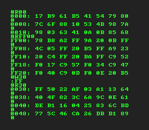
Woz wrote a 256-byte monitor program, commonly referred to as WozMon. It’s a simple utility which allows the operator to inspect RAM, modify RAM, and execute code in RAM or ROM. We’ve written our own version called MangoMon.
In our initial block, we use the $readmemh command to read the ROM data from virtual files in the IDE.
Verilog expects this data in textual format, one hexadecimal byte (or word) per line.
  initial begin
    $readmemh("mangomon.hex", monitor_rom);
  end
The file mangomon.hex contains our custom monitor program and CPU vectors.
Here are the commands:
Command |
Function |
|---|---|
|
Dump memory at address $aaaa |
Enter |
Dump next 8 bytes |
|
Write byte $bb at address $aaaa |
|
Jump to address $aaaa |
MangoMon fits into 256 bytes, just like Woz’s monitor program. How does our optimized code compare to his? Well, we saved maybe 8 bytes over his version, but we didn’t initialize the PIA chip (our design doesn’t simulate PIA configuration) and we don’t allow an ending address for memory dumps. Woz is still the king of optimization!
What Have We Learned?#
We’ve learned that we can simulate a 6502-based computer in your browser with Verilog and 8bitworkshop!
You can check out the source code in GitHub, or you can play around with it in 8bitworkshop.
Also check out our book “Designing Video Game Hardware in Verilog” where we design an entire game system using a custom 16-bit CPU.