Tiny Atari 2600 ROMs#
On the Atari 2600, a kernel is the term for the highly-optimized assembly code that draws the display, i.e. “races the beam”.
I was pondering a question: What’s the smallest Atari 2600 kernel you can write?
I found this AtariAge thread which packs entire ROMs into 32 bytes. Can we do better?
The typical approach#
Here’s how most well-programmed (i.e. “non-tiny”) Atari 2600 kernels operate.
Typical initialization#
The typical ROM starts with a variant of the CLEAN_START macro,
which initializes the TIA registers and RAM to zero.
The 6502 doesn’t guarantee registers or CPU flags are set to any
particular value on startup, so most programs set these explicitly
(although some use the uninitialized value for random numbers!)
                sei		; turn off interrupts
                cld            	; clear decimal flag
                ldx #0
                txa
                tay		; initialize registers
.CLEAR_STACK    dex		; push zeroes into $00-$FF range
                txs
                pha
                bne .CLEAR_STACK     ; SP=$FF, X = A = Y = 0
Typical vertical sync#
Our kernel minimally needs to emit three lines of vertical sync (VSYNC) and 259 additional lines of video to comply with the NTSC standard.
To emit the vertical sync signal, the optimized VERTICAL_SYNC macro is commonly
used, and it’s hard to do better:
                lda #%1110          ; each '1' bits generate a VSYNC ON line (bits 1..3)
.VSLP1          sta WSYNC           ; 1st '0' bit resets Vsync, 2nd '0' bit exits loop
                sta VSYNC
                lsr
                bne .VSLP1          ; branch until VSYNC has been reset
This is a clever routine that uses the bits in the A register as a counter, progressively shifting the bits until the register is zero. The VSYNC register only recognizes the second bit, giving us three lines of VSYNC:
VSYNC   0 0 0 0 1 1 1 0
VSYNC   0 0 0 0 0 1 1 1
VSYNC   0 0 0 0 0 0 1 1
-       0 0 0 0 0 0 0 1
-       0 0 0 0 0 0 0 0
                    ^
Typical VBLANK#
To implement the recommended standards, we need to set the VBLANK register above and below the main display, which should be about 192 scanlines high. VBLANK sets the video signal to the minimum level (black) which helps the CRT detect the vertical sync signal.
Using the PIA timer and TIMER macros, it might look like this:
NextFrame:
; 1 + 3 lines of VSYNC
	VERTICAL_SYNC
; 37 lines of underscan
	TIMER_SETUP 37
        TIMER_WAIT
; Re-enable output (disable VBLANK)
	lda #0
        sta VBLANK
; 192 lines of frame
	TIMER_SETUP 192
; ... draw the frame ...
        TIMER_WAIT
; Enable VBLANK (disable output)
	lda #2
        sta VBLANK
; 29 lines of overscan
	TIMER_SETUP 29
        TIMER_WAIT
; total = 262 lines, go to next frame
        jmp NextFrame
Lastly, we need the 6502 CPU vectors, which take up to six bytes:
	org $fffa
	.word Start
	.word Start
	.word Start
This basic kernel takes about 60-80 bytes of ROM. And we haven’t even drawn anything yet!
How can we reduce this to less than 32 bytes?
Tiny kernel: Initialization#
First, we can reduce the size of the initialization routine.
Unlike the emulator, a real Atari 2600 doesn’t initialize the TIA or RAM on startup to known values. To get a repeatable display, we have to at least set the TIA registers ($00-$3D) to something.
The AtariAge thread demo uses a clever loop that doesn’t depend on the initial value of the A register:
; stack pointer = $FD at startup
.loopClear:
    asl
    pha
    tsx
    bne    .loopClear
This loop starts with the A register containing an unknown value.
The trick here is that within eight loop iterations the asl instruction has cleared all the bits.
By the time the loop gets to the “important” memory locations in the TIA, the A register will contain zero, no matter what value it had at power-up.
This section takes only 5 bytes, compared to the CLEAN_START macro’s 11 bytes.
It doesn’t initialize the X or Y registers, so the first frame will likely be malformed, but that’s okay.
We don’t need sei (no interrupts) or cld (not using math operations) either.
Count 256 scanlines#
We don’t really need to emit a pre-frame and post-frame section separately.
Instead, we can use a loop to count off 256 scanlines after the VSYNC section.
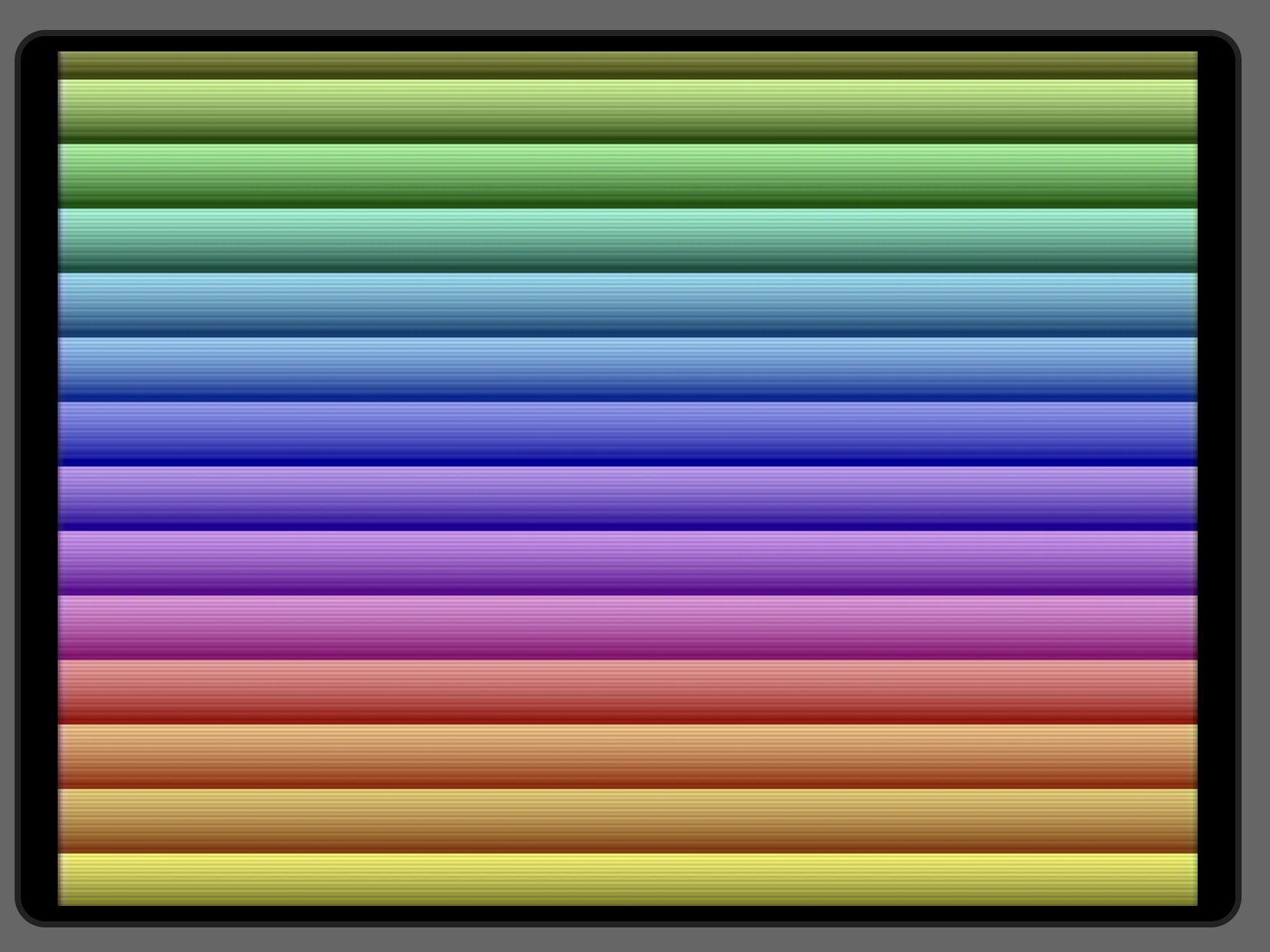
We can even store a value to the COLUBK register on each line, making a rainbow effect:
.doFrame:               ; main loop (7 bytes)
    sta WSYNC           ; wait for next scanline
    dey
    sty COLUBK		; rainbow effect
    bne .doFrame	; count 256 scanlines
After this loop completes, Y will be zero, so each run through will be exactly 256 scanlines. The VSYNC code takes 4 lines to complete, so this gives us 260 scanlines total. We’ve also ensured that the background color is set to zero at the end of the loop, which is pretty much the same as setting VBLANK.
If we want exactly 262 scanlines total, we can emit five VSYNC lines instead of three, even though this might make some CRTs slightly upset:
lda #%111110 ; each '1' bit generates a VSYNC ON line
Branch from CPU vectors#
The Atari 2600 only needs one CPU vector, the Reset vector at address $FFFC. The other two vectors are optional.
So we can use the final two bytes of the ROM for something – but what?
A branch instruction to the main loop would be ideal, but we have to skip over the Reset vector.
The (undocumented) NOP $xxxx instruction fits the bill:
    .byte  $0C            ; NOP, skip 2 bytes
    .word  Start          ; Reset vector (required)
    beq    .doVSYNC       ; Z=1, so always branch
This relies on the previous loop falling through the BNE instruction, so BEQ is guaranteed to branch.
A 17-byte kernel#
If we combine the initialization and main loops, we can get a smaller 17-byte kernel. Here’s the complete source code:
    processor 6502
    include "vcs.h"
    include "macro.h"
    include "xmacro.h"

    org $f800           ; pad ROM to 2K bytes
    brk
    org $ffff-16        ; start of tiny kernel

Start:
.doVSYNC:
    lda #%1110          ; each '1' bit generates a VSYNC ON line
.doLoop
    sta WSYNC           ; wait for next scanline
    sta VSYNC           ; set VSYNC
    sta COLUBK,x        ; initialize TIA and RAM
    lsr                 ; shift A to the right
    dex
    bne .doLoop         ; count 256 scanlines

    .byte $0C           ; NOP $xxxx (skip reset vector)
    .word Start         ; reset vector at $FFFC
    beq .doVSYNC        ; always branch
During each loop iteration, we set the VSYNC register to get the three-line VSYNC.
We also initialize the TIA and RAM with sta COLUBK,x.
We could have done sta $00,x or some other offset, but we start at COLUBK so that the background color is set while A has a non-zero value.
The TIA is mirrored at $40-$7C, so we’ll eventually get around to zeroing those addresses.
The address decoder also ensures that $100-$1ff is the same as $00-$ff.
This kernel counts 258 scanlines per frame, as a result of hitting the WSYNC register two additional times (at address $02 and at its mirror $42) during the 256-scanline loop.
The 17-byte kernel shows a solid color, but adding a stx COLUBK to make it an 19-byte kernel would show a rainbow display.
(Note: This adds two bytes to the code, so you have to change the line org $ffff-16 to org $ffff-18.)
Will actual CRTs be happy?#
Most emulators don’t simulate CRT circuitry exactly – there are so many generations of CRTs and TVs that it would be a fool’s errand anyway. What can we get away with and still show a stable image on actual CRTs?
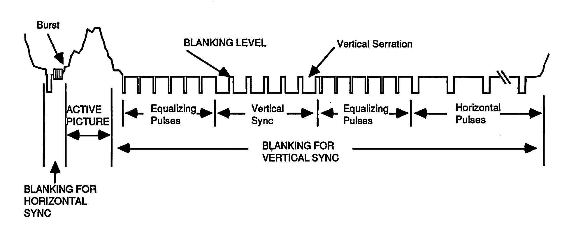
Classic CRTs have a sync separator circuit that isolates horizontal and vertical sync signals from the video signal. It looks for voltage levels below the “blacker than black” threshold, -0.3V relative to blanking level.
The sync separator circuit on older TVs use integrators (RC circuits) to detect the vertical interval. Depending on the values and tolerances of the analog components, the CRT may trigger on less than the recommended three lines of vertical sync.
If the CRT fails to lock onto the vertical sync signal, you’ll see a “rolling” effect on the screen. The vertical hold knobs on older televisions were meant to fix this symptom, allowing the free-running frequency of the internal oscillator to be tuned to more closely match the TV signal.
The NTSC standard recommends 6 lines of blank signal before and after the 3 lines of VSYNC. This helps the sync separator detect the VSYNC signal. We don’t do that in our tiny kernel, so this may cause problems with real CRTs.
The NTSC standard of 262 lines is recommended, but most CRTs tolerate slightly more or less, as long as the vertical sync signals are well-formed. Some Atari 2600 titles output as little as 248 or as many as 286 scanlines per frame.
Are tiny kernels useful?#
No, I just think they’re neat. But the lateral thinking required to write them is a useful skill to develop, especially in the field of retro programming. It’s also an interesting exercise in standards compliance – not many game consoles let you generate such a variety of malformed video signals!
p.s. I haven’t tried these kernels on an actual Atari 2600 – if you do, please leave a comment!