The Versatile Playfield Kernel#
In Atari 2600 programming, we struggle to draw two sprites and the playfield (background) within the 76-cycle budget of each scanline. For maximum-resolution single-line updates where we change parameters every scanline, we’d need to look up and write:
2 registers per sprite (color, bitmap) × 2 sprites = 4 registers
5 playfield registers (PF0, PF1, PF2, COLUPF, COLUBK)
That’s 9 register updates per scanline, which is difficult to achieve without additional hardware in the cartridge (like the DPC+ chip). So we look for clever shortcuts.
Drawing two sprites with single-line resolution already consumes most of our cycle budget, and we have precious few cycles left over for the playfield. The minimum-effort approach is to update the playfield every four scanlines, but this results in a blocky, low-resolution appearance.
What if we could choose which register to update on every scanline? This is the premise of the versatile playfield kernel, and it’s pretty simple.
Instead of hardcoding which register to update, we use two interleaved data arrays:
Register index table - which zero-page address to write to
Value table - what value to write
The kernel operates in a two-pass system:
Even scanlines: Read the register index from the data array and store it in the X register
Odd scanlines: Read the value from the data array and write it using
STA $00,X
; Y register == Y coordinate
; Even scanlines
lda (pointer),y    ; Read register index
tax                ; Store in X

; Odd scanlines
lda (pointer),y    ; Read value
sta $00,x          ; Write to the register
The data array contains pairs of bytes:
[register_index, value, register_index, value, ...]
For example:
[$0A, $FF, $0B, $AA, $0C, $55, ...] ; PF0=$FF, PF1=$AA, PF2=$55
Since we update the playfield every two scanlines, this gives the appearance of higher resolution compared to standard four-scanline kernels. However, we can only change a single register per pair of scanlines, which creates interesting constraints:
For bitmap registers (PF0/PF1/PF2): We can change at most 1/3 of the playfield bits per update.
For color registers (COLUPF/COLUBK): We can change either foreground or background per update, but not both.
With careful crafting, you can create some attractive designs, but with some limitations. For example, you can’t draw a level horizontal line because that requires updating all three PF registers at once. But you can set the foreground or background color so that both are identical, then any PF register changes are hidden until you change colors again.
The versatile playfield method takes no more than 9 cycles per scanline (assuming tables don’t cross page boundaries) so you should also be able to reposition player sprites without interrupting the background display.
Silly TIA Tricks#
The real power comes from the fact that we can write to any TIA register, not just playfield registers. This opens up a world of creative possibilities, for example:
Change
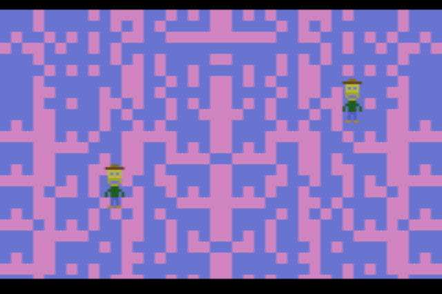
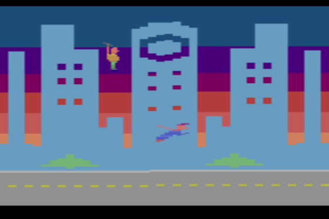
CTRLPFmid-screen to switch from reflected to non-reflected playfield mode, creating asymmetric patterns in specific regions. For example, the “Superdude” screenshot above uses asymmetric mode for the trees and road.Toggle the
SCOREbit inCTRLPF, which causes the left side of the playfield to use player 0’s color and the right side to use player 1’s color.Modify the
PFP(playfield priority) bit so sprites appear in front of the playfield in some areas and behind it in others.Change
NUSIZregisters as sprites move through certain vertical zones, causing them to stretch and duplicate for a fun-house mirror effect.Write to sprite bitmap or position registers for intentionally glitchy visual effects.
Mess with RAM to retrigger sprites or change their lookup table addresses.
Creating the Playfield Data#
A big drawback is that you cannot use traditional pixel editors to design these playfields. A standard bitmap editor doesn’t understand the constraint that only one register can change every two scanlines.
You could hand-code the lookup tables (tedious, every time) or write a custom editor (time-consuming, once). The middle option is to use a text-based parser that checks the constraints and builds the lookup tables. For example:
BITMAP               FG BG CTRL
.................... .. c0 ..
.................... .. .. 01
.................... 08 .. ..
.................... .. .. ..
..................xx .. .. ..
.....xxxx.........xx .. .. ..
.....xxxx........xxx .. .. ..
.....xxxx.......xxxx .. .. ..
.....xxxx.......xxxx .. .. ..
.....xxxx.......xxx. .. .. ..
.....xxxx.......xx.. .. .. ..
.....xxxx.......x... .. .. ..
.....xxxx.......x..x .. .. ..
.....xxxx.......x.xx .. .. ..
.....xxxx.......x.xx .. .. ..
.....xxxx.......x.xx .. 60 ..
.....xxxxxxx....x.xx .. .. ..
.xx..xxxxxxx....x.xx .. .. ..
.xx..xxxxxxx....x..x .. .. ..
Collision Detection#
The versatile kernel makes it relatively easy to do platform collision detection.
We are looking for a certain change in the PF0/PF1/PF2 registers.
First, we look up the appropriate playfield register and mask for a given X position in a pair of lookup tables:
  lda xpos          ; X coordinate to check
  clc
  adc #6
  lsr
  lsr
  tay               ; Y = X div 4
  lda PFCollideMask,y
  sta bitmask       ; expected bit mask
  lda PFCollideReg,y
  sta expected_reg  ; expected PF register
  lda #176        ; adjust for kernel size
  sec
  sbc ypos          ; subtract b/c table is backwards
  and #$fe
  tay               ; Y = index into playfield table
Now we see if the playfield table has the expected register change:
lda (pointer),y    ; Get register to check
cmp expected_reg  ; Is it the right register?
bne no_collision
dey
lda (pointer),y    ; Get mask byte
and bitmask        ; Apply bit mask
beq no_collision   ; Zero = no collision
We could even combine the PF0/1/2 register change with another.
For example, we only trigger a collision if we also see a COLUPF color change preceding the playfield register change.